本实验所配置的模型已开源至 Github: HaofeiMa/E05_Robotiq-2f-85
1 模型准备
1.1 机器人Solidworks模型转URDF
本仿真实验使用大族E05机器人 和Robotiq 2f-85夹爪
该部分参考以下视频
首先下载机器人模型,并转换为URDF。
(1)安装sw_urdf_exporter插件
下载sw_urdf_exporter插件:http://wiki.ros.org/sw_urdf_exporter ,注意下载最新的就行,最新的也支持以前版本的Solidworks。
关闭 Solidworks。
运行 sw2urdfSetup.exe ,自行安装即可。
(2)为机器人添加基准轴(旋转轴)
以此选择六个圆柱面,确定六个旋转轴方向。
(3)导出URDF
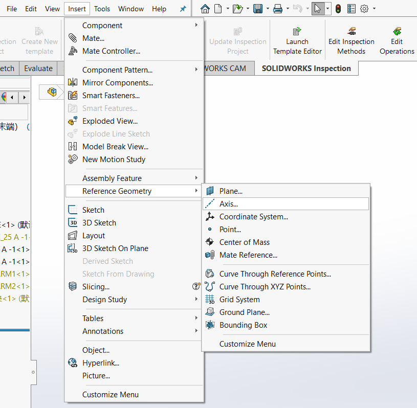
查看是否有【工具-最下面File-Export as URDF】,如果有的话,直接点击打开,如果没有,则打开【工具-插件】,在最下面打开Sw2URDF插件的两个√。
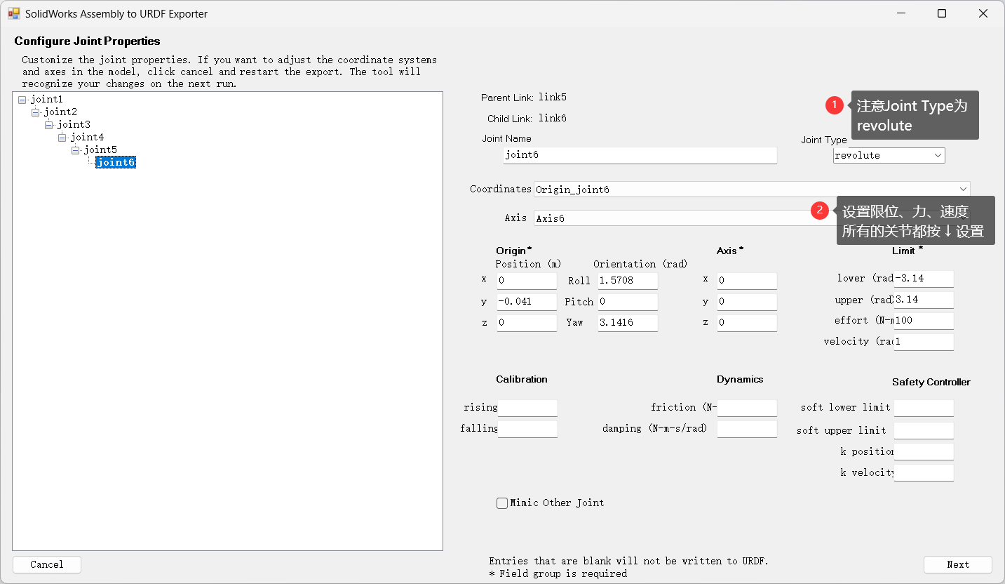
按照以下过程,创建base_link和link1-6
然后点击Preview and Export
然后点击Next和Export URDF and Mesh,它会将我们的URDF模型以功能包的形式保存到设置的位置。
注意创建完成后,一定要检查最后一个坐标系是否是在机器人末端连接法兰的中心,因为后续添加夹爪需要这个坐标系,如果不是,需要自己手动调整坐标系的位置,重新生成URDF
1.2 ROS 中查看模型
不需要使用 Gazebo 的可直接跳到第 2 节(2 模型导入 Mujoco)
创建一个工作空间
1
2
3
mkdir -p catkin_robot/src cd catkin_robot/src catkin_init_workspace
将功能包复制到src目录下
回到 catkin_robot 目录下,编译工作空间
运行测试程序
1 2 source devel/setup.bash roslaunch e05 display.launch
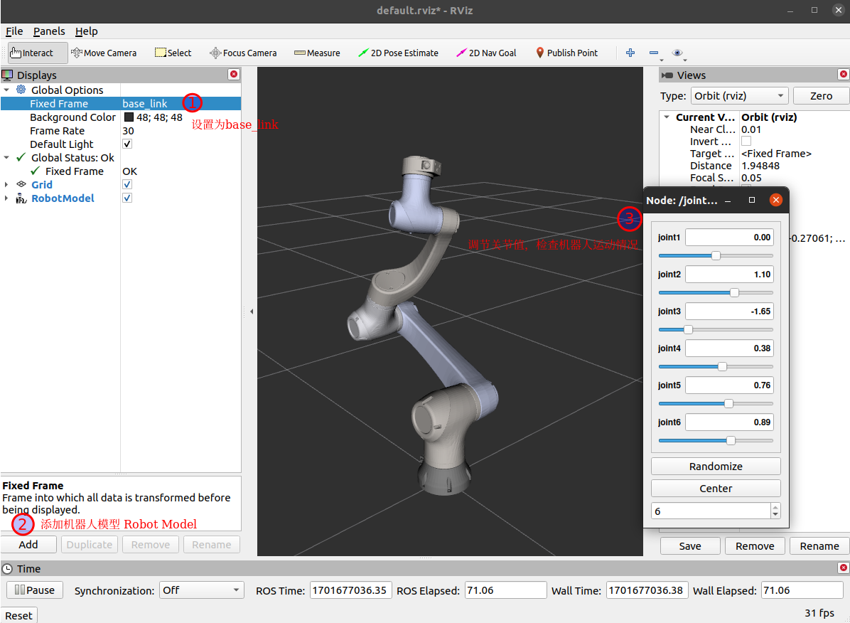
将 Fixed Frame 改为 base_link,点击左下角的 Add,添加一个 Robot Model,可以看到机器人正常显示在 Rviz 界面中,拖动进度条即可控制机械臂各关节运动。
1.3 添加 Robotiq 2f-85 夹爪
(1)准备夹爪环境
进入工作空间的src目录
1 2 cd src git clone https://github.com/ros-industrial/robotiq.git
在自己的机械臂的功能包的urdf文件夹中,新建一个common.gazebo.xacro文件
1
2
cd src/e05/urdf gedit common.gazebo.xacro
添加以下内容
1 2 3 4 5 6 7 8 9 10 <?xml version="1.0" ?> <robot xmlns:xacro ="http://wiki.ros.org/xacro" > <gazebo > <plugin name ="ros_control" filename ="libgazebo_ros_control.so" > </plugin > </gazebo > </robot >
为了方便表示,我在e05.urdf最后添加了一个ee_link
1 2 3 4 5 6 7 8 9 10 11 12 13 14 15 16 17 <link name ="ee_link" > <visual > <origin xyz ="0 0 0" rpy ="0 0 0" /> <geometry > <sphere radius ="0.01" /> </geometry > <material name ="" > <color rgba ="1 0 0 1" /> </material > </visual > </link > <joint name ="ee_joint" type ="fixed" > <origin xyz ="0 0 0" rpy ="0 0 0" /> <parent link ="link6" /> <child link ="ee_link" /> </joint >
再新建一个xacro文件,(例如我的机械臂功能包名字为e05)
添加如下内容,注意修改Gazebo支持和E05机械臂部分自己的机械臂功能包名称,以及夹爪与机械臂连接部分的第一行的parent,我这里连接在了link6也就是末端上。
1 2 3 4 5 6 7 8 9 10 11 12 13 14 15 16 17 18 19 20 21 22 23 24 25 26 27 28 29 30 31 32 33 34 35 36 37 38 39 40 41 42 43 44 45 46 47 48 49 50 51 52 53 54 55 56 57 58 59 60 61 62 63 64 65 66 67 68 69 70 71 72 73 74 75 76 77 78 79 80 81 82 83 84 85 86 <?xml version="1.0" ?> <robot xmlns:xacro ="http://www.ros.org/wiki/xacro" name ="e05" > <xacro:arg name ="transmission_hw_interface" default ="hardware_interface/PositionJointInterface" /> <xacro:include filename ="$(find e05)/urdf/e05.urdf" /> <xacro:include filename ="$(find e05)/urdf/common.gazebo.xacro" /> <xacro:macro name ="transmission_block" params ="joint_name" > <transmission name ="tran1" > <type > transmission_interface/SimpleTransmission</type > <joint name ="${joint_name}" > <hardwareInterface > hardware_interface/PositionJointInterface</hardwareInterface > </joint > <actuator name ="motor1" > <hardwareInterface > hardware_interface/PositionJointInterface</hardwareInterface > <mechanicalReduction > 1</mechanicalReduction > </actuator > </transmission > </xacro:macro > <xacro:transmission_block joint_name ="joint1" /> <xacro:transmission_block joint_name ="joint2" /> <xacro:transmission_block joint_name ="joint3" /> <xacro:transmission_block joint_name ="joint4" /> <xacro:transmission_block joint_name ="joint5" /> <xacro:transmission_block joint_name ="joint6" /> <link name ="world" /> <joint name ="world_joint" type ="fixed" > <parent link ="world" /> <child link = "base_link" /> <origin xyz ="0.0 0.0 0" rpy ="0.0 0.0 0.0" /> </joint > <xacro:include filename ="$(find robotiq_2f_85_gripper_visualization)/urdf/robotiq_arg2f_85_macro.xacro" /> <xacro:include filename ="$(find robotiq_85_description)/urdf/robotiq_85_gripper.urdf.xacro" /> <gazebo > <plugin name ="gazebo_grasp_fix" filename ="libgazebo_grasp_fix.so" > <arm > <arm_name > ur5_gripper</arm_name > <palm_link > link6</palm_link > <gripper_link > gripper_finger1_finger_tip_link</gripper_link > <gripper_link > gripper_finger2_finger_tip_link</gripper_link > <gripper_link > gripper_finger2_knuckle_link</gripper_link > <gripper_link > gripper_finger1_knuckle_link</gripper_link > <gripper_link > gripper_finger1_inner_knuckle_link</gripper_link > <gripper_link > gripper_finger2_inner_knuckle_link</gripper_link > </arm > <forces_angle_tolerance > 150</forces_angle_tolerance > <update_rate > 130</update_rate > <grip_count_threshold > 2</grip_count_threshold > <max_grip_count > 8</max_grip_count > <release_tolerance > 0.005</release_tolerance > <disable_collisions_on_attach > true</disable_collisions_on_attach > <contact_topic > __default_topic__</contact_topic > </plugin > </gazebo > <xacro:robotiq_85_gripper prefix ="" parent ="ee_link" > <origin xyz ="0 0 0" rpy ="0 ${-pi/2} 0" /> </xacro:robotiq_85_gripper > </robot >
修改原来的launch文件,这里我为了后续方便,将原来的display.launch重命名了display_e05_with_gripper.launch,这里主要修改<param name="robot_description" command="$(find xacro)/xacro '$(find e05)/urdf/e05.xacro'" /> 这一行,添加刚刚创建的xacro文件。
1 2 3 4 5 6 7 8 <launch > <arg name ="model" /> <param name ="robot_description" command ="$(find xacro)/xacro '$(find e05)/urdf/e05.xacro'" /> <node name ="joint_state_publisher_gui" pkg ="joint_state_publisher_gui" type ="joint_state_publisher_gui" /> <node name ="robot_state_publisher" pkg ="robot_state_publisher" type ="robot_state_publisher" /> <node name ="rviz" pkg ="rviz" type ="rviz" args ="-d $(find e05)/urdf.rviz" /> </launch >
(2)Rviz中查看机器人
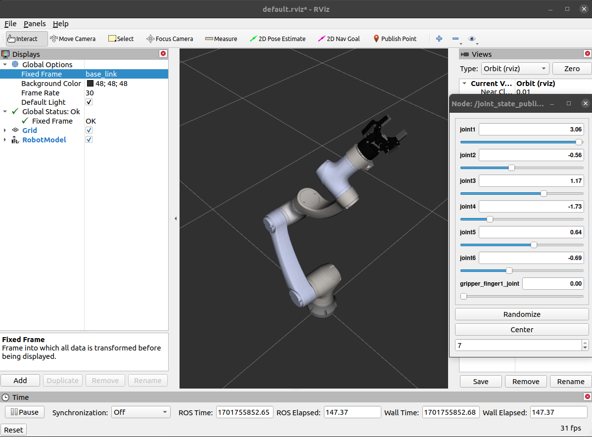
1 2 3 4 cd catkin_motion catkin_make source devel/setup.bash roslaunch e05 display_e05_with_gripper.launch
左下角Add,添加机器人模型RobotModel。
左侧Fixed Frame选择base_link,即可看到机器人了。
(3)Gazebo中查看机器人
创建一个gazebo_e05_with_gripper.launch文件,内容参考如下:
1 2 3 4 5 6 7 8 9 10 11 12 13 14 15 16 17 18 19 20 21 22 23 24 <launch > <arg name ="gui" default ="true" doc ="Starts gazebo gui" /> <arg name ="paused" default ="false" doc ="Starts gazebo in paused mode" /> <include file ="$(find gazebo_ros)/launch/empty_world.launch" > <arg name ="world_name" default ="$(find gazebo_ros)/launch/empty_world.world" /> <arg name ="paused" value ="$(arg paused)" /> <arg name ="gui" value ="$(arg gui)" /> </include > <node name ="tf_footprint_base" pkg ="tf" type ="static_transform_publisher" args ="0 0 0 0 0 0 base_link base_footprint 40" /> <include file ="$(find e05)/launch/display_e05_with_gripper.launch" /> <node name ="spawn_gazebo_model" pkg ="gazebo_ros" type ="spawn_model" args ="-urdf -param robot_description -model robot -z 0" respawn ="false" output ="screen" /> <node name ="fake_joint_calibration" pkg ="rostopic" type ="rostopic" args ="pub /calibrated std_msgs/Bool true" /> </launch >
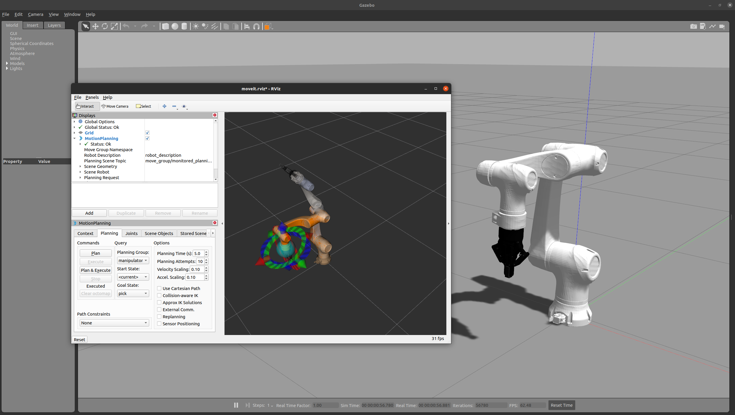
此时启动launch文件,可以看到gazebo环境中机器人。
下面的创建moveit驱动,在mujoco中不需要,请直接跳到 2 模型导入mujoco
1.4 创建MoveIt驱动
此部分参考该文章 。
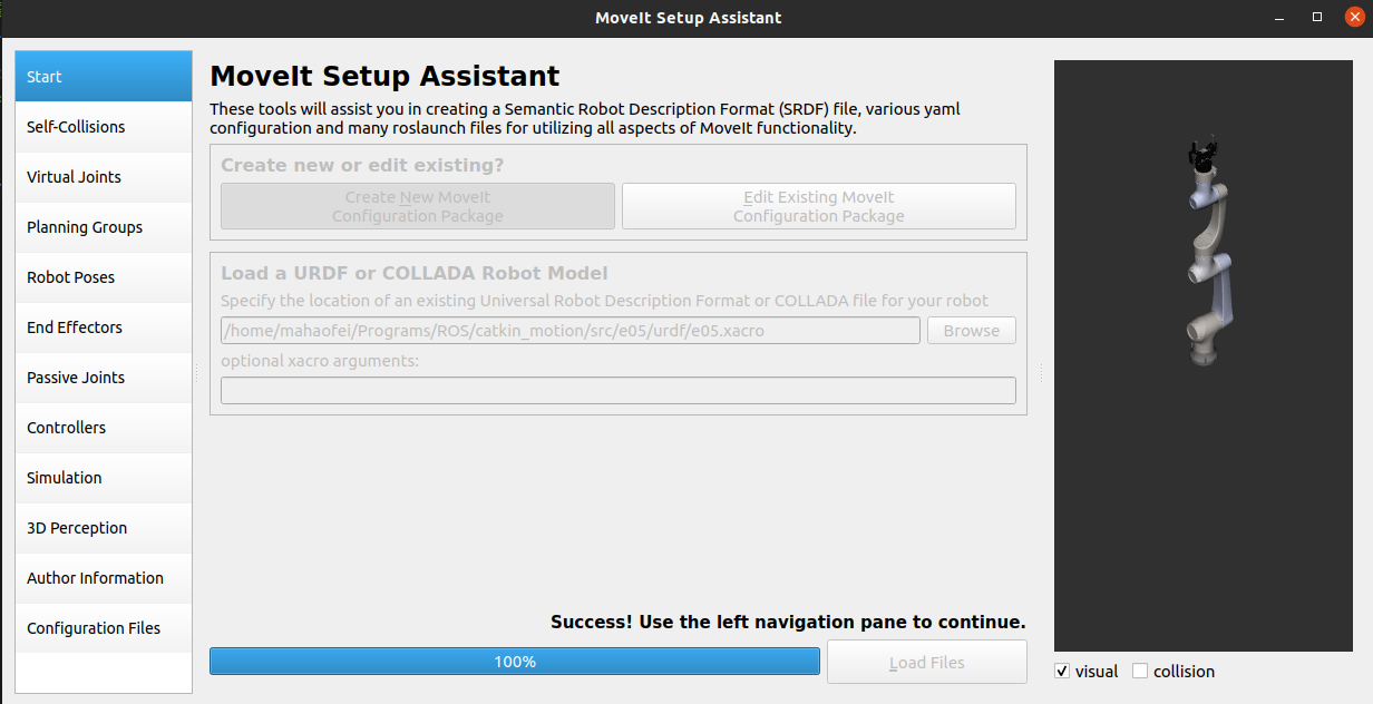
启动moveit设置助手
1 rosrun moveit_setup_assistant moveit_setup_assistant
选择Create New Moveit Configuration Package,选择自己的e05.xacro文件,点击Load Files
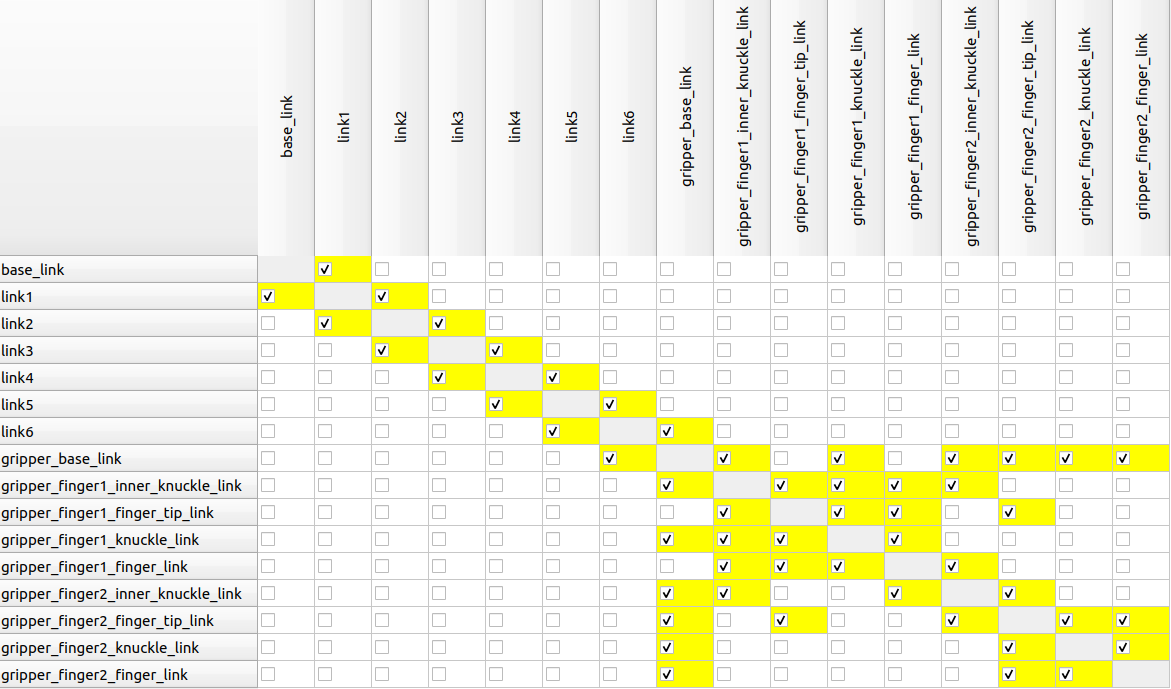
左侧第二个的Self-Collisions是检查碰撞,一定将所有有可能发生碰撞的都勾选上,不然后续会出错。
第三个Virtual Joints一般也不需要。
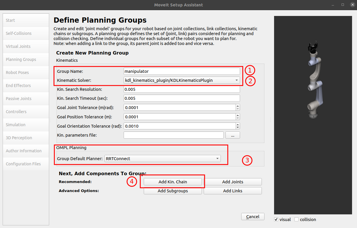
第四个Planning Groups是最重要的,我们需要设置,点击Add Group,分别配置机器人和末端夹爪。
机械臂:
Group Name一般填manipulator就行
运动学求解器,选择kdl
路径规划算法,默认选择RRT Star就行
点击Add Kin. Chain,Baselink选择 base_link,Tiplink选择ee_link
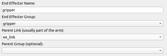
末端夹爪的Group Name填上gripper,其它的都不用选。
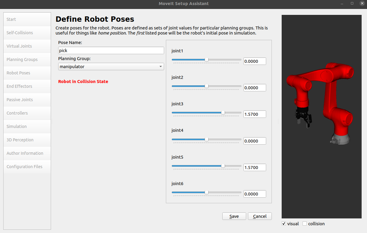
第五个Robot Poses可以添加一些常用位置,便于我们快速使机器人运动到这些位置,例如
up:机器人初始的竖直向上
pick:机器人准备夹取
open:夹爪打开
close:夹爪关闭
第六个End Effectors,按下图设置就行
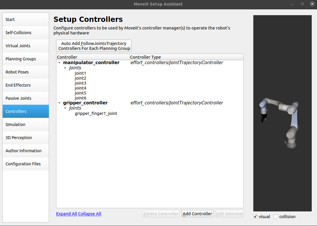
点击Controllers,点击左上角自动生成
点击倒数第二个Author Information,填写名字和邮箱,不一定是真实的,但是不填无法生成功能包
最后Generate Package就可以了(在src目录下新建一个e05_moveit文件夹,选择此文件夹生成)
测试rviz是否能控制机器人
1 2 3 catkin_make source devel/setup.bash roslaunch e05_moveit demo.launch
测试gazebo是否能联动
1 roslaunch e05_moveit demo_gazebo.launch
测试时遇到了Rviz中的机械臂可以正常做规划和执行,但是Gazebo中机械臂没有反应 的问题,解决方法参考此文章
2 模型导入Mujoco
2.1 修改URDF
在现有模型的xacro或urdf中的开头,添加下面的tag
1 2 3 4 5 6 <mujoco > <compiler meshdir ="../meshes_mujoco/" balanceinertia ="true" discardvisual ="false" /> </mujoco >
创建一个文件夹e05/meshes_mujoco,将所有模型的stl文件放到这个文件夹下。
从xacro文件生成urdf文件的命令(如果有urdf文件则不需要此步):
1 rosrun xacro xacro --inorder e05.xacro > e05.urdf
检查urdf文件:
在RViz中可视化:
1 roslaunch e05 display.launch model:=path/to/your/urdf/file
2.2 生成基本模型
在确认URDF模型没有问题后,进入MuJoCo的可执行文件夹内执行命令进行转换
1 cd ~/.mujoco/mujoco210/bin
官方说明可以转换成三种模型.mjb/.txt/.xml,我们一般用xml的格式。
1 ./compile /path/to/model.urdf /path/to/model.xml
测试生成的基本模型
1 ./simulate /path/to/model.xml
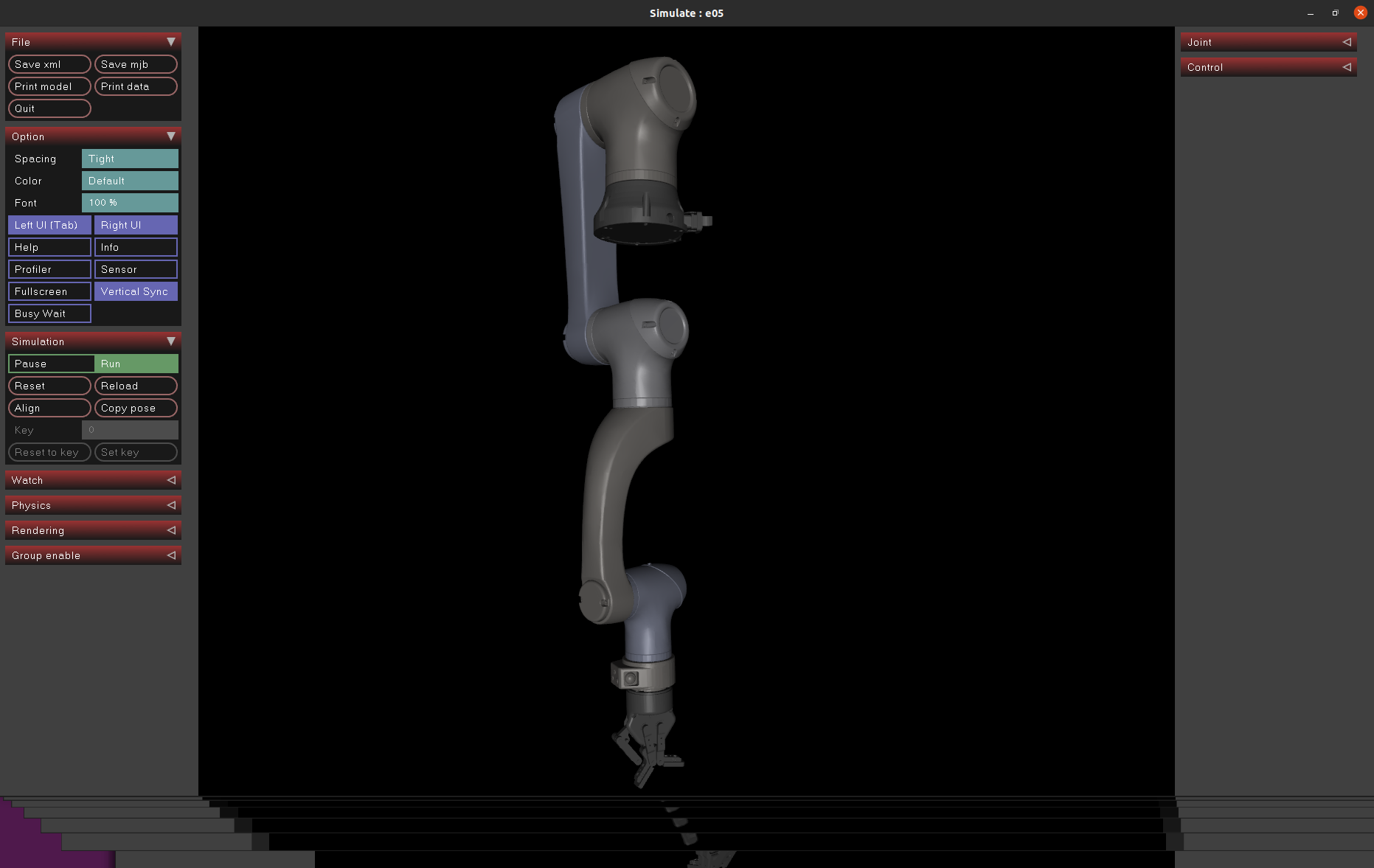
可以看到我们的机器人出现在了仿真环境中,虽然会发现我们的模型直接瘫倒,但是这是因为没有添加actuator等配置。
由于夹爪出现问题,一直无法使用,因此替换了vikashplus/robotiq_sim 的夹爪。
添加完成后的e05_mujoco.xml代码如下:
1 2 3 4 5 6 7 8 9 10 11 12 13 14 15 16 17 18 19 20 21 22 23 24 25 26 27 28 29 30 31 32 33 34 35 36 37 38 39 40 41 42 43 44 45 46 47 48 49 50 51 52 53 54 55 56 57 58 59 60 61 62 63 64 65 66 67 68 69 70 71 72 73 74 75 76 77 78 79 80 81 82 83 84 85 86 87 88 89 90 91 92 93 94 95 96 97 98 99 100 <mujoco model ="e05" > <compiler angle ="radian" meshdir ="../meshes_mujoco/" /> <size njmax ="500" nconmax ="100" /> <asset > <mesh name ="base_link" file ="e05/base_link.STL" /> <mesh name ="link1" file ="e05/link1.STL" /> <mesh name ="link2" file ="e05/link2.STL" /> <mesh name ="link3" file ="e05/link3.STL" /> <mesh name ="link4" file ="e05/link4.STL" /> <mesh name ="link5" file ="e05/link5.STL" /> <mesh name ="link6" file ="e05/link6.STL" /> <texture type ="skybox" builtin ="gradient" rgb1 ="0.3 0.5 0.7" rgb2 ="0 0 0" width ="512" height ="3072" /> <texture type ="2d" name ="groundplane" builtin ="checker" mark ="edge" rgb1 ="0.2 0.3 0.4" rgb2 ="0.1 0.2 0.3" markrgb ="0.8 0.8 0.8" width ="300" height ="300" /> <material name ="groundplane" texture ="groundplane" texuniform ="true" texrepeat ="5 5" reflectance ="0.2" /> </asset > <default > <default class ="E05" > <joint damping ='200' /> </default > <default class ="E05e" > <joint damping ='100' /> </default > </default > <include file ="robotiq-2f-85-assets.xml" /> <worldbody > <light diffuse ="0.6 0.6 0.6" pos ="0 0 3" /> <light diffuse ="0.6 0.6 0.6" pos ="0 -0.3 3" dir ="0 0.2 -0.8" directional ="true" /> <geom name ="floor" size ="0 0 0.05" type ="plane" material ="groundplane" /> <geom type ="mesh" contype ="0" conaffinity ="0" group ="1" rgba ="0.501961 0.501961 0.501961 1" mesh ="base_link" /> <geom type ="mesh" rgba ="0.501961 0.501961 0.501961 1" mesh ="base_link" /> <body name ="link1" pos ="0 0 0.0735" > <inertial pos ="-0.0218175 -1.34618e-05 0.0953928" quat ="0.696024 -0.147787 -0.14991 0.686467" mass ="2.58559" diaginertia ="0.0143616 0.0141793 0.00506835" /> <joint class ="E05" name ="joint1" pos ="0 0 0" axis ="0 0 1" limited ="true" range ="-3.14159 3.14159" /> <geom type ="mesh" contype ="0" conaffinity ="0" group ="1" rgba ="0.772549 0.752941 0.733333 1" mesh ="link1" /> <geom type ="mesh" rgba ="0.772549 0.752941 0.733333 1" mesh ="link1" /> <body name ="link2" pos ="0 0 0.1465" quat ="0.5 -0.5 -0.5 0.5" > <inertial pos ="4.42659e-06 -0.15814 0.130501" quat ="0.491565 0.508215 -0.508335 0.491606" mass ="1.21311" diaginertia ="0.0159807 0.0154676 0.00149746" /> <joint class ="E05" name ="joint2" pos ="0 0 0" axis ="0 0 -1" limited ="true" range ="-3.14159 3.14159" /> <geom type ="mesh" contype ="0" conaffinity ="0" group ="1" rgba ="0.792157 0.819608 0.933333 1" mesh ="link2" /> <geom type ="mesh" rgba ="0.792157 0.819608 0.933333 1" mesh ="link2" /> <body name ="link3" pos ="0 -0.38 0" quat ="0.707107 0 0 0.707107" > <inertial pos ="-0.0414786 1.14213e-05 0.0194164" quat ="0.601987 0.371892 0.373044 0.600122" mass ="1.53239" diaginertia ="0.00608826 0.00587729 0.00215529" /> <joint class ="E05" name ="joint3" pos ="0 0 0" axis ="0 0 -1" limited ="true" range ="-3.14159 3.14159" /> <geom type ="mesh" contype ="0" conaffinity ="0" group ="1" rgba ="0.866667 0.866667 0.890196 1" mesh ="link3" /> <geom type ="mesh" rgba ="0.866667 0.866667 0.890196 1" mesh ="link3" /> <body name ="link4" pos ="0 0 0" quat ="0.5 -0.5 0.5 -0.5" > <inertial pos ="3.8238e-05 -0.0589656 -0.257081" quat ="0.988248 -0.152858 -0.000415939 -0.000860755" mass ="0.475189" diaginertia ="0.00538322 0.0052745 0.000778119" /> <joint class ="E05e" name ="joint4" pos ="0 0 0" axis ="0 0 1" limited ="true" range ="-3.14159 3.14159" /> <geom type ="mesh" contype ="0" conaffinity ="0" group ="1" rgba ="0.772549 0.752941 0.733333 1" mesh ="link4" /> <geom type ="mesh" rgba ="0.772549 0.752941 0.733333 1" mesh ="link4" /> <body name ="link5" pos ="0 0 -0.42" quat ="0.707105 -0.707108 0 0" > <inertial pos ="1.42418e-06 0.0365906 -0.0159722" quat ="0.527641 0.849468 0.000113207 -7.90953e-05" mass ="0.811919" diaginertia ="0.00229898 0.00217056 0.000742684" /> <joint class ="E05e" name ="joint5" pos ="0 0 0" axis ="0 0 1" limited ="true" range ="-3.14159 3.14159" /> <geom type ="mesh" contype ="0" conaffinity ="0" group ="1" rgba ="0.792157 0.819608 0.933333 1" mesh ="link5" /> <geom type ="mesh" rgba ="0.792157 0.819608 0.933333 1" mesh ="link5" /> <body name ="link6" pos ="0 0.155 0" quat ="0.707105 -0.707108 0 0" > <inertial pos ="-4.84703e-06 0.00109667 -0.0032406" quat ="0.999926 0.0120786 2.3554e-05 -0.00120144" mass ="0.75038" diaginertia ="0.00129697 0.00122959 0.00051245" /> <joint class ="E05e" name ="joint6" pos ="0 0 0" axis ="0 0 -1" limited ="true" range ="-3.14159 3.14159" /> <geom type ="mesh" contype ="0" conaffinity ="0" group ="1" rgba ="0.776471 0.756863 0.737255 1" mesh ="link6" /> <geom type ="mesh" rgba ="0.776471 0.756863 0.737255 1" mesh ="link6" /> <geom size ="0.01" contype ="0" conaffinity ="0" group ="1" rgba ="1 0 0 1" /> <include file ="robotiq-2f-85-chain.xml" /> </body > </body > </body > </body > </body > </body > </worldbody > <actuator > <position name ="joint1" ctrllimited ="true" ctrlrange ="-3.14159 3.14159" joint ="joint1" kp ="4000" /> <position name ="joint2" ctrllimited ="true" ctrlrange ="-1.57 1.57" joint ="joint2" kp ="3000" /> <position name ="joint3" ctrllimited ="true" ctrlrange ="-3.14159 3.14159" joint ="joint3" kp ="3000" /> <position name ="joint4" ctrllimited ="true" ctrlrange ="-3.14159 3.14159" joint ="joint4" kp ="2000" /> <position name ="joint5" ctrllimited ="true" ctrlrange ="-3.14159 3.14159" joint ="joint5" kp ="2000" /> <position name ="joint6" ctrllimited ="true" ctrlrange ="-3.14159 3.14159" joint ="joint6" kp ="2000" /> </actuator > </mujoco >
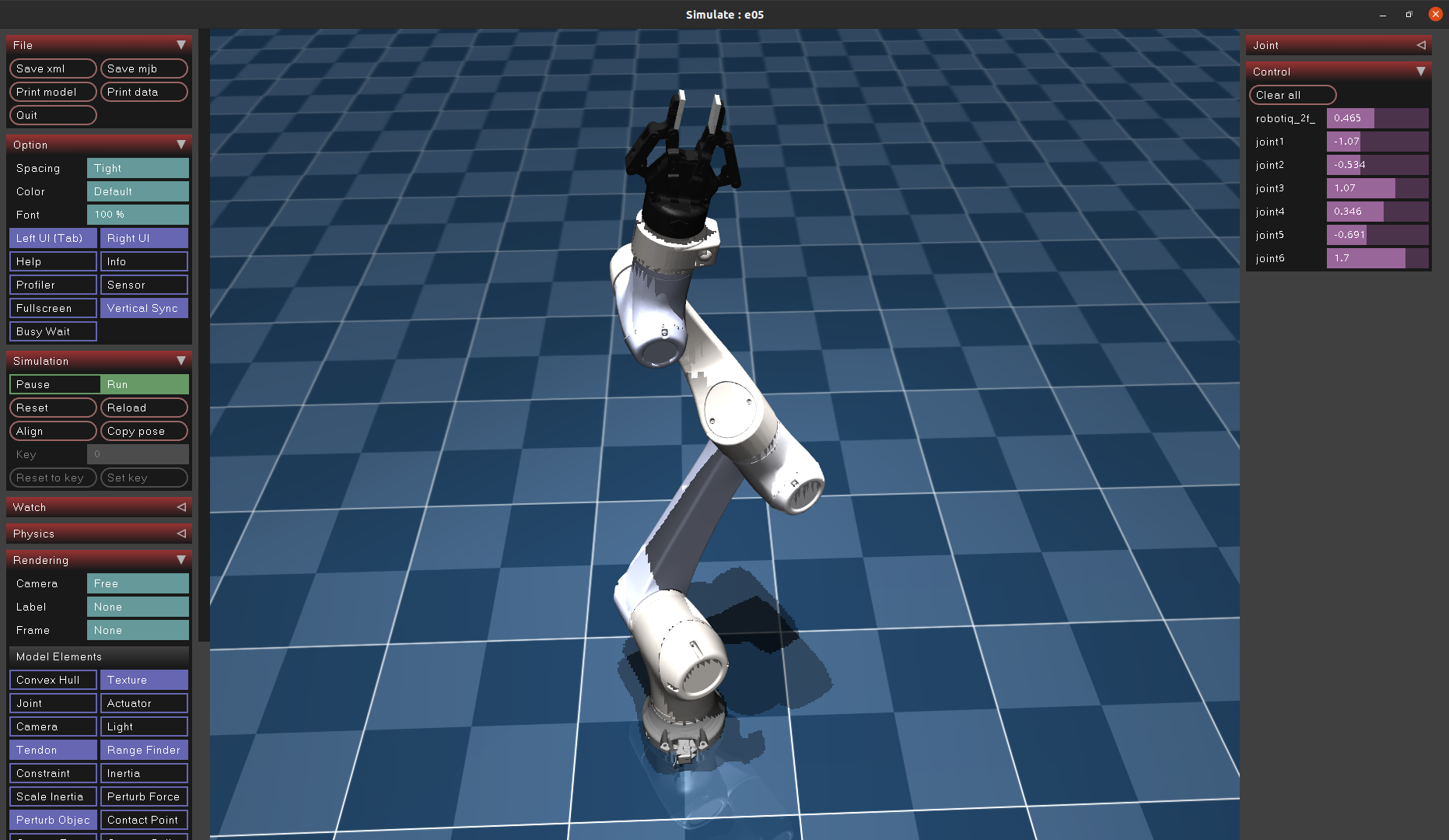
添加完成后效果如下:
注意,需要在每个 joint 标签中加入 damping 属性,例如 damping='200' ,否则会出现模型持续抖动闪烁,无法控制的问题。
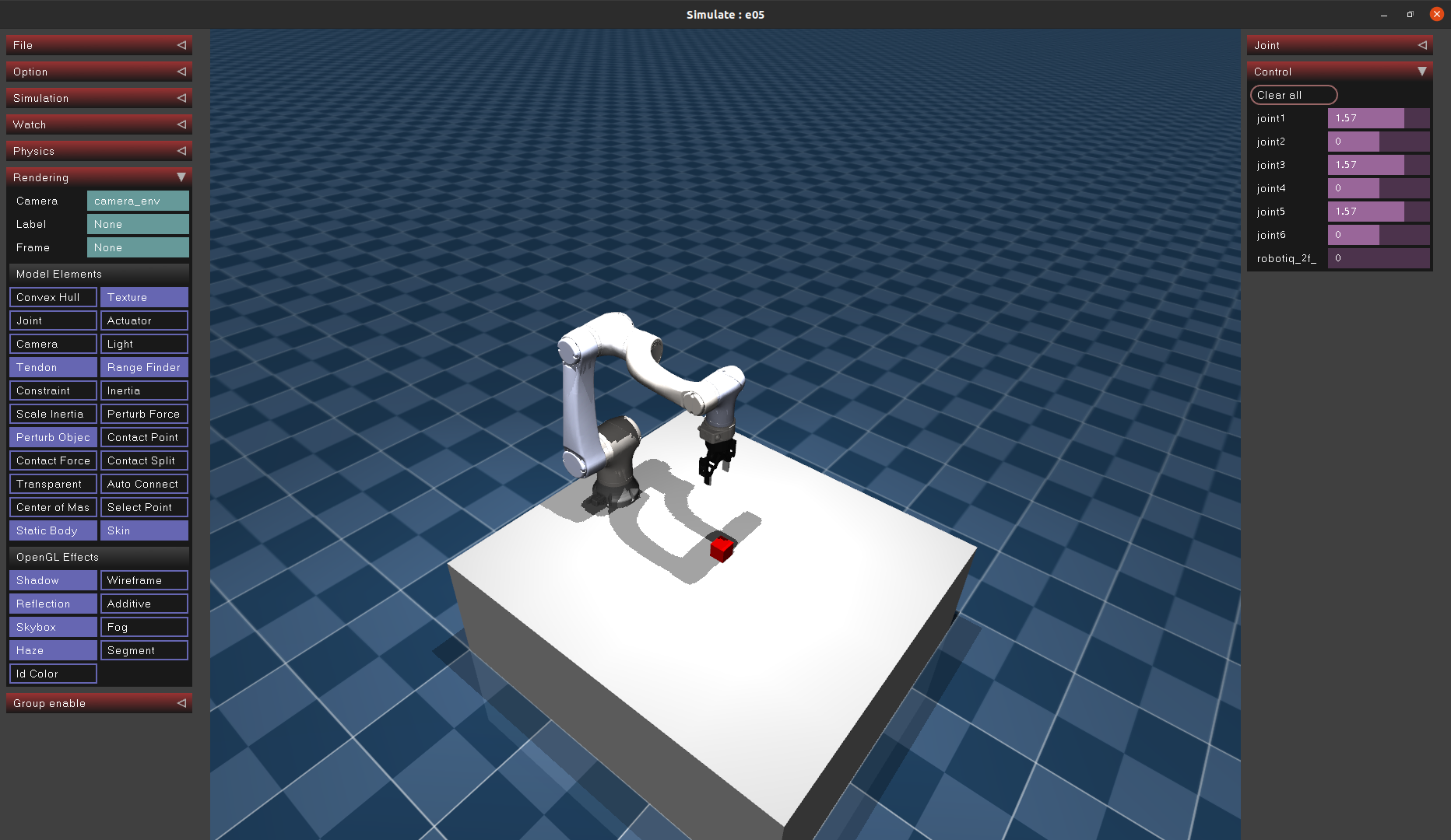
整理文件结构,添加桌子、小方块,移动机器人位置和相机视角,最后得到下面的仿真环境。具体代码已开源至Github :
3 Mujoco 常用命令
3.1 模型加载与初始化配置
模型加载:
1 model = mujoco_py.load_model_from_path("path/to/.xml" )
创建mujoco仿真实例:
1 sim = mujoco_py.MjSim(model)
渲染设置:
1 2 3 4 5 6 7 8 9 viewer = mujoco_py.MjViewer(sim) lookat = [1.27998563 , 0.68635066 , 0.55350562 ] for idx in range (3 ): viewer.cam.lookat[idx] = lookat[idx] viewer.cam.distance = 1.4547035766991275 viewer.cam.azimuth = 134.95215311004816 viewer.cam.elevation = -32.488038277512022
初始姿态设置:
1 2 3 4 5 6 7 8 9 10 11 12 13 14 15 initial_qpos = { 'joint1' : np.pi/2 , 'joint2' : 0 , 'joint3' : np.pi/2 , 'joint4' : 0 , 'joint5' : np.pi/2 , 'joint6' : 0 , 'robotiq_2f_85_right_driver_joint' : 0 , 'object0:joint' : [1 , 0.45 , 0.425 , 1. , 0. , 0. , 0. ], } for name, value in initial_qpos.items(): sim.data.set_joint_qpos(name, value) sim.forward()
主函数调用方法:
1 2 3 while True : sim.step() viewer.render()
3.2 基本信息查询与设置
(1)body
打印body位置与姿态
1 2 3 4 5 body_idx = sim.model.body_name2id("link6" ) print (sim.data.body_xpos[body_idx])print (sim.data.body_xquat[body_idx])
(2)site
打印site位置与姿态
1 2 print (sim.data.get_site_xpos('site_name' ))print (sim.data.get_site_xquat('site_name' ))
(3)joint
打印joint值:
1 2 joint_idx = model.joint_name2id("joint_name" ) print (sim.data.qpos[model.jnt_qposadr[joint_idx]])
设置joint值
1 sim.data.set_joint_qpos("joint_name" , value)
(4)actuator
打印actuator状态
设置actuator值
1 sim.data.ctrl[actuator_index] = value
(5)mocap
打印mocap位置和姿态:
1 2 print (sim.data.mocap_pos)print (sim.data.mocap_quat)
设置mocap位置和姿态
1 2 3 4 5 6 7 sim.data.mocap_pos[:] = np.array([x, y, z]) sim.data.mocap_quat[:] = np.array([quat_1, quat_2, quat_3, quat_4]) sim.data.set_mocap_pos('mocap_name' , np.array([x, y, z])) sim.data.set_mocap_quat('mocap_name' , np.array([quat_1, quat_2, quat_3, quat_4]))
参考链接:
SUES木鸢机甲工作室. SolidWorks模型导出urdf (古月居老师). Bilibili Robot Learning. MuJoCo的机器人建模. 知乎 MuJoCo官方论坛 MoJoCo官方文档 vikashplus/robotiq_sim.git


 微信支付
微信支付 支付宝
支付宝